Summary
The 2×4s are the dome’s main support, and so here’s an entire (and pretty long) page devoted to them. Perhaps I should summarize the results here:
- The 2×4s are sufficiently strong to support the dome in a 60 MPH wind.
- Holes in the 2×4s must be set back 1 to 2 inches from the end of the wood member (the exact amount depends on the width of the 2×4 after its end is angled).
Still coming along? Well, buckle up!
You sure? Last chance . . . here we go.
Introduction
Each of the dome’s 2×4 members is in compression or in tension, depending on the loads that the structure faces. We can analyze both of these conditions. All members need to resist some amount of bending. This condition can be analyzed, too.
Remember that in allowable-stress design, actual stresses are compared to allowable stresses to determine whether a design is safe.
Tension in 2×4s
2×4s in tension are described by the allowable tensile stress, FT. The allowable tensile strength of a select structural hemlock fir 2×4 is 925 psi. Just how much tensile load can such a 2×4 withstand?

So the tensile strength of a 2×4 is outrageously strong. It’s the bolt hole that is the weakest part. Tearing through a bolt hole in a 2×4 requires shearing two planes, one on each side of the hole. Resistance to this shearing is quantified by the allowable shear stress, ![]() , which for all grades of hemlock fir is 75 psi.
, which for all grades of hemlock fir is 75 psi.
Remember that in Part 1 the shear load of a bolt was calculated to be 437 pounds. It makes no sense to require the bolt hole in the 2×4 to be stronger than the bolt, and so below I calculate the backset of the hole in the 2×4 for a tensile load of 437 pounds.

Since tearing through a hole requires failure of the shear planes on both sides of the hole, the shear area of the hole backset is just half of the value calculated above.
![]()
For a long bolt going through the entire 3.5″ height of a 2×4 (5-plate attachment), the backset can be calculated from the shear-plane area.

(Note: I’m assuming that both ends of the bolt are supported, which is not true with the plate attachment used here. So I really should increase the backset to compensate.)
For a bolt going through the end of 2×4 that is cut at an angle (3-plate attachment), the backset is a function of the height remaining after the cut. For a conservative measurement, I’ll use the thickness of the narrowest part of the cut, ignoring the thin wedge of material that results from the cut angle.
| Height of Cut 2x4 | Required Hole Backset |
|---|---|
| 3.5 in | 0.84 in |
| 3.0 | 0.97 |
| 2.5 | 1.67 |
| 2.0 | 1.46 |
| 1.5 | 1.94 |
The result is that the hole in the end of each 2×4 should be backset by 1 to 2 inches in order for the 2×4 to be as strong as the bolt that attaches it to the joint plate.
Compression in 2×4s
A 2×4 in compression is considered a column, which is a configuration that we can analyze.
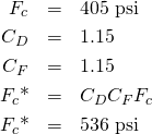
Allowable compressive stress is calculated below.

The dimensions of an 8-foot 2×4 are

Assume that the attachment holes in the 2×4s are 2 inches back from the ends. Then the apparent length of the column, between these supports, is 4 inches shorter.
![]()
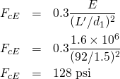
The elastic modulus of select structural hemlock fir 2×4s is ![]() .
.
The allowable compressive stress, ![]() , is
, is

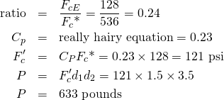
Then the allowable compressive load is calculated here.

Yeah! So the 2×4 is strong enough in compression.
A final note on the column analysis. An 8-foot 2×4 violates the “slenderness ratio” for columns, which recommends an L/d ratio of 50 maximum. The L/d of a 92-inch 2×4 is 61. I’m just going to ignore this for now. A possible solution is to brace the 2×4s, if I can convince myself that it’s really necessary. But given that the capacity of the column exceeds the requirements by almost 45%, I don’t think I’m going to worry too much.
Bending in 2×4s
The bending analysis is incredibly complicated, so I’m just going to summarize the calculations here.
- Calculate the total wind load on a member. I considered one of the 8′ members that is facing the wind. It has the largest wind load
 .
. - Maximum shear is half of 143 pounds:
 .
. - Calculating the maximum moment is more complicated because the load is distributed non-uniformly (the shade fabric is in triangular panels, and so the load at the member ends is zero, but the load in the middle is large). After doing lots of math,
 .
. - Allowable bending stress is calculated by multipling the base allowable bending stress
 by two bending adjustment factors. One factor,
  , compensates for the short load duration (less than two months). The other factor,
  , adjusts the base bending stress for the size of a 2×4. Finally, after multiplying everything together,
  .
. - The required section modulus is calculated at the point of maximum stress. It is the ratio of the maximum moment and the allowable bending stress.
 .
. - The section modulus of a 2×4 is
 , which is three times the required value, and so the 2×4 will withstand the wind load.
Everything Together
All loading on a 2×4 must be combined simultaneously. The worst case is a 2×4 that is in compression and is withstanding a wind load. There is an equation for this. It specifies that the total stress in a member must be less than total allowable stress.
The equation, below, is a real beauty.

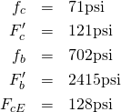
I calculated all of its values:

I obtained the result that even the longest 2×4 will withstand the wind load. The analysis assumes that holes in the 70% shade cloth decrease the wind load by 6% (the amount necessary to meet the equation’s condition).
I assumed that either end of the 2×4s could rotate, since only a single bolt holds each end, but if two bolts attach each end, or if the joint plates otherwise prevent 2×4 rotation, then in the analysis I get to decrease the 2×4 length by 35% (or increase the member thickness). This observation suggests that joint plates that prevent rotation allow narrower members while maintaining the same strength. It even helps put the slenderness ratio into the right region.
Conclusion
Using 2×4s for this structure will be okay in a 60-MPH wind.
Wow! You made it to the end. Congratulations!